
A rework or soldering station can have a variety of equipment depending on the users needs. One thing that most tools require is power, and every station should have fume extraction and good lighting. I got tired of reaching to turn multiple things every time I needed to work on something so I put together a power controller for my soldering tools.
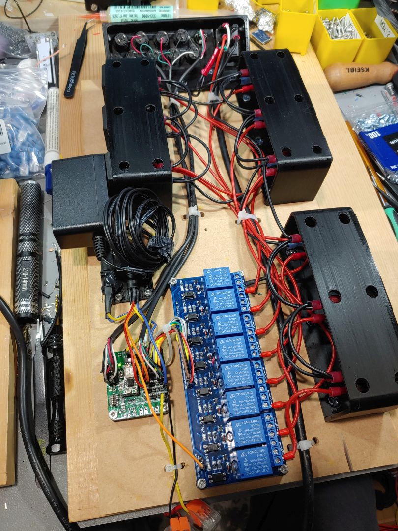
I mounted everything to a sheet of 1/4″ MDF. 3D printed housings hold outlet sockets for different devices. A large relay board controls power to the sockets. The front panel has a main power switch and a variety of push buttons. The main power switch controls power to the relays, as well as a DC power supply for the micro controller board and power to the desks LED lamps. The controller is a custom dev board I use that has a SAMD51, but it could just as easily be any Arduino board. The code is about as simple as it gets: detect button presses, turn outputs on and off. You can connect the buttons are relays however you need for your work flow. I have different buttons for each soldering iron and hot air, then when any of those tools are on it also turns on the fume extraction fan.
One additional feature is a PIR motion sensor placed in the control panel. This ensures I don’t leave and forget to turn off any hot tools. If there is no motion for 10 mins it shuts all the relays off.

The soldering irons are simple, the relay just turns them on and off. The hot air is a bit more tricky. Normally when you turn off the hot airs power switch the heat shuts off put the air keeps running to cool it down. I wanted to maintain this feature, so instead of just killing the input power, I installed another relay board inside the hot air tool to double as its normal power switch. I added a 4 wire stereo jack to the back of the hot air tool’s case and to my control board so I can connect them with a regular 4 wire stereo cable (similar to how the Hakko soldering iron’s tool detection is connected). This way the hot air is connected to power like normal, but the control board can switch on and off it’s power switch like you would use it manually, and it maintains the cool down feature.


Overall the system is quite useful and makes the soldering jobs faster and easier. I realized when it was done that I should have used buttons with LEDs in them to easily be able to tell which was activated at the time. It’s not hard to remember which button does what after a while, but it would have been better. I’ve ordered some and I’ll update the control panel sometime.